Mob & Whatsapp: +86-166-5035-8998

Copper Head Conductor Rail
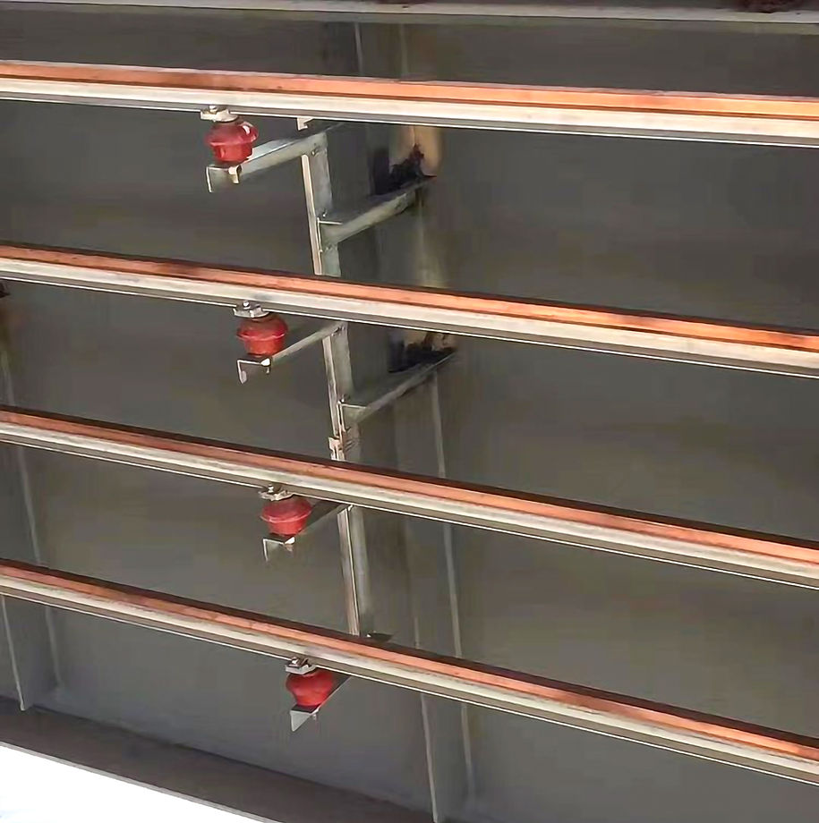
Description:
The copper head conductor steel rail is a mobile power supply system applied to deliver electrical power to moving equipment such as gantry cranes. Typically constructed from trapezoidal copper bars combined with channel steel, or "T"-shaped copper busbars integrated with grooved aluminum profiles, the copper-head conductor rail features a robust structure, excellent electrical conductivity, and long service life. It is widely used in industrial and mining enterprises, ensuring stable and safe power transmission to mobile equipment.

Features:
-
Reliable operation without power interruption.
-
Suitable for harsh environments such as high temperatures, heavy dust, and corrosive gases.
-
High strength, resistant to bending and deformation, capable of withstanding strong short-circuit currents.
-
Current capacity can be customized to user requirements, reaching over 3000A, with voltage ratings exceeding 5kV.
-
Copper or copper-aluminum conductors significantly reduce power loss during transmission.
-
When equipped with auxiliary cables, it can form a low-impedance conductor system, reducing wire impedance significantly.
-
Power feeding can be configured from either the top or bottom side.
-
Extra-large heat dissipation surface, compact and simple structure, and is easy to install and maintain.

Notes for Installation:
-
Standard Length:
-
Supplied in fixed lengths of 6 meters under normal circumstances.
-
-
Bracket Spacing:
-
Insulating support brackets are typically installed at 3-meter intervals.
-
-
Types of Conductor Rails:
-
Single-line type: No additional model code is used.
-
Dual-line equal-feed type: Indicated by JGH-□II.
-
-
Installation Methods:
-
Top-feed installation
-
Bottom-feed installation
-
Custom mounting methods are also available based on user requirements.
-
-
Bracket Support Adjustments:
-
While standard bracket spacing is 3 meters, reinforcement measures can be implemented to extend the spacing under special conditions.
-
-
Phase-to-Phase Distance:
-
Standard configuration: 400 mm between phases.
-
For low-impedance conductor rails: spacing can be increased to 450 mm.
-